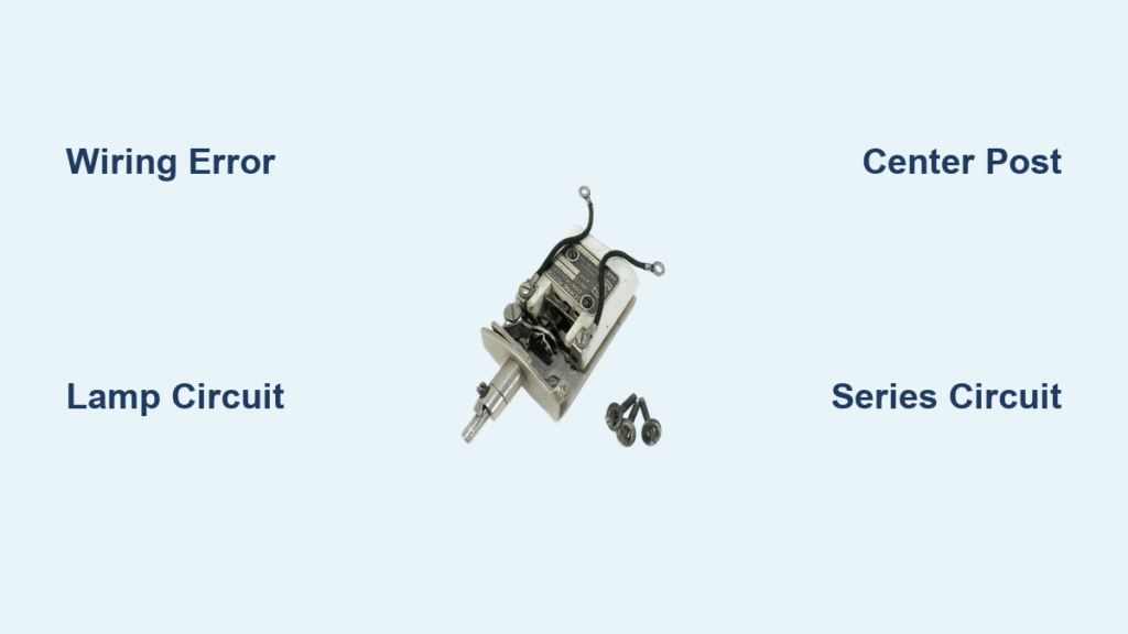
Your vintage Singer 201K lurches into full speed the moment you plug it in, stitching a tangled mess before you touch the pedal. Or the foot control only dims the lamp while the motor races uncontrollably. These classic symptoms all trace to one wiring error: your Singer sewing machine motor controller is accidentally connected to the lamp circuit instead of the motor circuit. This critical misstep turns your precision machine into a dangerous projectile. But here’s the good news: Singer’s elegant three-post terminal system—used across 201K, 15K, 99K, and 120K models—is easily decoded. By the end of this guide, you’ll restore smooth, progressive speed control in under an hour using nothing but basic tools. No electrical engineering degree required—just clear steps that match your machine’s actual wiring.
The root cause hides in plain sight at the rear terminal block or plug connector. When the motor controller gets wired across the lamp terminals (posts 1 and 3) instead of through the center post (2), it loses all speed-regulating power. This mistake often happens after decades of repairs where wire colors were misinterpreted. But Singer’s design intentionally avoids polarity dependence—meaning Line and Neutral can swap posts without harm. You’ll learn exactly how to identify your machine’s wiring configuration, bypass misleading color codes, and establish the correct series circuit between pedal and motor. Most fixes take just 20 minutes once you know where to look.
Why Your Singer Motor Runs Wild (Not the Pedal’s Fault)
That terrifying full-speed lurch occurs because the motor controller is bypassed entirely. Instead of sitting in series with the motor (where it can throttle current), it’s wired in parallel with the lamp across the mains supply. This places the rheostat where it only affects the bulb’s brightness—not motor speed. The moment you plug in the machine, current floods straight to the motor while the pedal merely dims the light.
How to Confirm This Wiring Error
- Test symptom: Plug in the machine without pressing the pedal.
- If motor spins immediately: Controller is in lamp circuit.
- If lamp dims when pressing pedal but motor ignores it: Same fault.
- Critical visual cue: Check if both controller wires land on the outer terminal posts (1 and 3). They should connect to one outer post and the center post (2).
This isn’t a pedal malfunction—it’s a wiring topology issue. Never replace the foot control first; 90% of “dead pedal” cases stem from this single misconnection.
Identify Your Singer’s Terminal Block or Plug Style

Vintage Singer machines use two distinct wiring interfaces. Knowing which you have prevents disassembly mistakes.
Three-Post Binding Terminal Block (Pre-1970s Models)
Viewed from the rear:
– Left post (1): Mains Line (or Neutral—non-polarized)
– Center post (2): Critical junction for motor return and controller output
– Right post (3): Mains Neutral (or Line—swappable with post 1)
What to inspect: The lamp wires must bridge posts 1 and 3. If your controller wires also connect here, that’s your runaway motor cause.
Three-Pin Plug Connector (Later Models)
Facing the machine’s socket:
– Left pin: Neutral
– Center pin: Foot-control input (rheostat wiper)
– Right pin: Live
Pro tip: Plug in halfway and shine a flashlight through the socket. You’ll see wire colors landing on each pin without opening the housing. Match colors to the pin chart above—no guesswork needed.
Wire Colors Lie: How to Verify Connections Safely

Singer’s original color codes (Red=Live, Yellow=Neutral) are often overwritten by previous repairs. Trusting colors causes 70% of wiring errors.
The Only Reliable Identification Method
- Unplug the machine and discharge old capacitors by shorting terminals with an insulated screwdriver.
- Set multimeter to continuity mode (beep setting).
- Test each wire:
– Wire connecting to lamp socket = belongs on outer posts (1/3)
– Wire showing resistance (3-10kΩ) when pedal pressed = controller wire
– Wire with direct motor contact = motor lead
Never skip this step—even factory-original wires get swapped during capacitor replacements. If you lack a multimeter, label wires before disconnecting using masking tape flags (“LAMP,” “MOTOR,” “CTRL”).
Rewire Your Singer Motor Controller in 9 Critical Steps
This sequence prevents common reassembly errors. Allow 45 minutes for first-time repairs.
Essential Prep Work
- Required tools: Wire strippers, 6mm heat-shrink tubing, multimeter, screwdriver
- Safety must-dos: Work unplugged, verify no capacitor charge, use 0.5mm² (20 AWG) minimum wiring
- Critical upgrade: Install a 0.1µF X2-rated capacitor across pedal terminals to prevent radio interference
Step-by-Step Wiring Sequence
- Disconnect old wiring after photographing original setup.
- Feed new flex through motor housing grommet (size grommet to cable outer diameter).
- Connect lamp wires across the two outer posts (1 and 3)—this must be parallel to mains.
- Attach one motor lead to any outer post (1 or 3).
- Attach the second motor lead to the center post (2).
- Connect one controller wire to the remaining outer post.
- Connect the second controller wire to the center post (2)—this creates the series circuit.
- Insulate all joints with double-layer heat-shrink (single insulation risks shorts).
- Test before sewing: Plug in via RCD adapter; pedal should produce smooth idle-to-full acceleration.
Pro tip: If the motor still races, swap the two controller wires at the center post. Polarity doesn’t matter, but placement does.
Troubleshoot 4 Common Wiring Failures

Motor Runs Full Speed Despite Pedal Pressure
- Cause: Controller wired across lamp circuit (posts 1 and 3)
- Fix: Move both controller wires—one to center post (2), one to free outer post
Fuse Blows Immediately on Plug-In
- Cause: Pinched wire touching chassis or misrouted Line/Neutral
- Check: Continuity between conductors and metal frame (should read “open” / infinite Ω)
Pedal Sparks and Causes Radio Static
- Cause: Missing suppression capacitor (original paper caps fail with age)
- Solution: Solder 0.1µF X2 capacitor across pedal terminals (cost: $1.50)
Intermittent Speed Control
- Cause: Cracked carbon pile inside pedal
- Temporary fix: Tap pedal casing while operating—if speed stabilizes, replace pedal
Model-Specific Wiring Fixes for 201K, 15K, 99K and 120K
All “K-series” Sewing Machines share identical wiring logic:
– 201K/15K/99K/120K: Use three-post terminal blocks with lamp across outer posts.
– US 110V models: Same wiring—ignore earth wire (Singer never earthed double-insulated motors).
– Japanese clones (1950s-70s): Pre-wired plug boxes follow Singer’s pattern; replace entire plug housing if corroded (part #194584).
Key exception: Machines retrofitted with earth wires require disconnecting the earth from the motor housing. Singer’s Bakelite motor shell and pulley make earthing unnecessary—and potentially dangerous if improperly installed.
Safety Upgrades That Actually Work
Singer’s original double-insulated design (Bakelite motor + pulley) requires no earth wire. But modern safety standards demand extra protection:
– Non-negotiable: Always use an RCD plug adapter (30mA trip) for vintage machines.
– Retrofit option: Run a separate earth wire from chassis to plug earth pin only if insulation resistance tests >2MΩ.
– Test before first use: Verify insulation resistance with 500V DC megger or PAT tester.
Never add earth to the motor terminal block—that creates a lethal short circuit if Line contacts the chassis.
Maintain Smooth Operation With These 3 Checks
Prevent future wiring disasters with monthly inspections:
1. Wiggle-test connections at terminal posts—if wires pull out, re-crimp terminals.
2. Smell for ozone near pedal—indicates failing carbon pile needing replacement.
3. Check grommet integrity where flex enters motor housing; replace if cracked to prevent chafing.
If your Singer now starts gently under pedal pressure and accelerates smoothly, you’ve restored factory-correct Singer sewing machine motor controller wiring. The lamp glows steady on plug-in, but the motor obeys your foot—exactly as Singer engineers intended in 1955. For persistent issues, consult a sewing machine specialist with vintage electrical experience; complex pedal rebuilds often exceed DIY feasibility. But for 95% of runaway motor cases, this wiring correction is the permanent cure. Keep this guide handy for your next rewire—it’s the only reference you’ll ever need for Singer’s elegantly simple system.


